What is Ideal Transformer ?
An ideal transformer is a imaginary transformer which has the following properties :
 |
| Ideal Transformer |
- It's primary and secondary winding resistance are negligible.
- The core has infinity permeability (μ) so that negligible mmf is required to establish the flux in the core.
- It's leakage flux and leakage inductance are zero. The entire flux is confined to the core and links both winding.
- There are no losses due to resistance, hysteresis and eddy currents. Thus, the efficiency is 100%.
It is to be noted that practical (commercial) transformer has none of these properties inspite of the face that its operation is close to ideal.
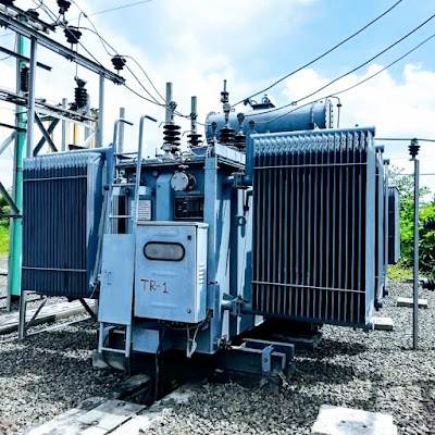
An ideal iron core transformer is shown in fig below.
It consists of two coils wound in the same direction on a common magnetic core. The winding connected to the supply, V1, is called the primary. The winding connected to the load, Z1, is called the secondary.
Since the ideal transformer has zero primary and zero secondary impedance, the voltage induced in the primary E1 is equal to the applied voltage V1. Similarly, the secondary voltage V2 is equal to the secondary induced voltage E2. The current I1 drawn from the supply is just sufficient to produce mutual flux øm and the required magnetomotive force (mmf) I1T1 to overcome the demagnetizing effect of the secondary mmf I2T2 as a result of connected load.
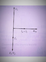
By Lenz's law E1 is equal and opposite to V1. Since E2 and E1 are both induced by the same mutual flux, E2 is in the same direction as E1 but opposite to V1. The magnetizing current Iμ lags V1 by 90° and produces øm in phase with Iμ. E1 and E2 lag øm by 90° and are produced by øm. V2 is equal in magnitude to E2' and is opposite to V1.
No-load phasor diagram of the ideal transformer shown in fig below:
For an ideal transformer, if
a = transformation ratio = turn ratio
then, a = T1÷T2 = E1÷E2 = V1÷V2= I2÷I1
Therefore,. I1T1 = I2T2
Since the ideal transformer has zero primary and zero secondary impedance, the voltage induced in the primary E1 is equal to the applied voltage V1. Similarly, the secondary voltage V2 is equal to the secondary induced voltage E2. The current I1 drawn from the supply is just sufficient to produce mutual flux øm and the required magnetomotive force (mmf) I1T1 to overcome the demagnetizing effect of the secondary mmf I2T2 as a result of connected load.
By Lenz's law E1 is equal and opposite to V1. Since E2 and E1 are both induced by the same mutual flux, E2 is in the same direction as E1 but opposite to V1. The magnetizing current Iμ lags V1 by 90° and produces øm in phase with Iμ. E1 and E2 lag øm by 90° and are produced by øm. V2 is equal in magnitude to E2' and is opposite to V1.
No-load phasor diagram of the ideal transformer shown in fig below:
 |
| No-load phasor diagram of an ideal transformer |
For an ideal transformer, if
a = transformation ratio = turn ratio
then, a = T1÷T2 = E1÷E2 = V1÷V2= I2÷I1
Therefore,. I1T1 = I2T2
E1I1 = E2I2 = S2 = S1 V1I1 = V2I2 = S2 = S1


1 comments:
Click here for commentsPora khub valo laglo brother
Please do not enter any spam link in the comment box. ConversionConversion EmoticonEmoticon