How to measure insulation resistance or earth resistance by Megger ?
Insulation resistance of an electrical equipment refers to the resistance between conducting part and earth, expressed in megaohms. This insulation resistance can be also be measured between two circuit separated by insulation.

 |
Image credit by gettyimages
|
Insulation resistance measured by Megger. Megger consists of a built in megaohm meter and a d.c. generator. The generator is driven by hand or by a motor.
 |
| Megger for insulation resistance test |
Megger (Megaohm meters) are available for d.c. voltage of 500V and 1000V. Generally in practice 500V Megger are used.
Testing of Earth Continuity :
Earthing can be tested with the help of test lamp or the Megger. To proceed for the test with lamp. Connect one end of test lamp to the phase wire and other end with the metal parts of the fitting. If the fitting is properly earthed, then the lamp will glow.
To proceed for the test with Megger, connect the line wire with the metal parts of the fitting and the earth wire of Megger with some sound earth connection. If the fitting is properly earthed then on rotating the handle of Megger, the pointer will indicate zero.
Difference between insulation resistance and earth resistance
Insulation resistance is measured between conductor and earth. It is of the order of several 10/1000 Mega ohms or infinity for healthy insulation. It is measured by means of megger (mega-ohm meter), with built-in DC generator.
Earth resistance is measured for a earthed metallic body or neutral point. It is measured by means of earth resistance tester. For good effective earthing, the earth resistance should be of the order of 0.5 ohm.
Measurements of Insulation Resistance Between Conductors
This test is taken up to know the standard of insulation of wires and cables used in the installation, i.e., insulation should be sufficient enough to avoid any possible leakage of current to earth. The leakage of the current to earth should not exceed 1/5 thousand part or 0.02% of the full load current. The test is conducted on whole installation on the main switch.
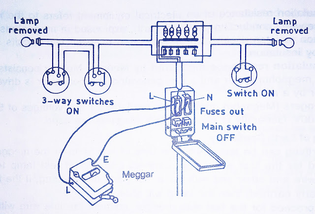
Before performing insulation resistance test between conductor the position of main switch, fuses and switches should be as under:
- Main switch in off position with fuses out.
- All switches in on position.
- All lamps and other appliances should be removed.
- The fuses beyond the main switch should be in position.
 |
Conductor-to-Conductor test
|
The line terminal of the Megger is connected to phase terminal of the installation and the ‘E’ (earth) terminal of megger is connected to neutral link. The handle of megger is turned on steady speed to generate the required testing voltage. The insulation resistance so measured on the megger should not be more than that specified for the test to earth
50 MΩ / No of outlet points + Switches
But in any case value should not be less than 0.5 MΩ and more than 1 MΩ.
Insulation Resistance Test Between Insulation And Earth
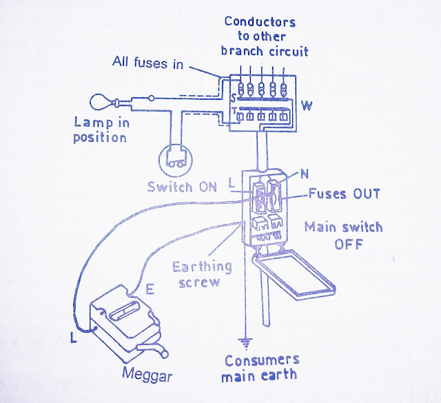
This test is performed to check the insulation test between installation and earth. Before performing insulation resistance test between installation and earth the following points should be followed.
- The main switch in OFF position.
- All switches in ON position.
- The fuses beyond the main switch should be in position.
- The lamp and other equipment in their position.
- The phase and neutral terminal connected to each other and connect them to the line terminal of the Megger with a wire. The earth terminal of the megger is connected to earth continuity conductor.
 |
| Conductor to earth test |
Procedure :-The line terminal of megger marked (L) is connected to the short circuit point in the main switch and the earth terminal marked (E) is connected to the earth continuity conductor. The handle of tester is turned with a high speed continuously to generate sufficient voltage. The reading on the dial indicates the value of insulation resistance. During rotation the megger handle, do not touch the leads otherwise severe shock will be observed
The value of insulation resistance thus measured should not be less than 0.5 mega ohms (MΩ).
Earth Resistance Tester
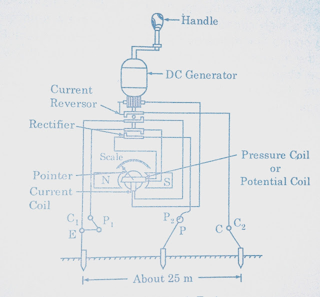
This test is conducted with the help of earth tester. The instruments consist of four terminals marked P1 C1 & P2, C2. P1 & C1, are linked together. When testing a single earth electrode, temporary spike connected to C2 should be about 25 meters from the point under test and temporary potential spike connected to P2 about 12.5 meters from the point to be tested.
 |
| Earth Tester |
Put the tester horizontally on a firm stand away from any strong magnetic field, so firmly that the tester should not shake when its handle is turned. Use the switch provided in the instrument and set it to a suitable scale. Now turn the handle in proper direction at the required speed. Note the reading on scale. Three readings are taken from different sources. The value should not be more than 1Ω. Take the mean of all three readings.
This is dummy text. It is not meant to be read. Accordingly, it is difficult to figure out when to end it. But then, this is dummy text. It is not meant to be read. Period.


Please do not enter any spam link in the comment box. ConversionConversion EmoticonEmoticon