
We have already discussed Construction of DC Motor in our previous post. Now we discussed about working principle of DC motor.


Basis Principle :-
The DC motor is the device which converts the direct current into the mechanical work. It works on the principle of Lorentz Law, which states that the current carrying conductor placed in a magnetic and electric field experience a force. And that force is called the Lorentz force. The Flemming left-hand rule gives the direction of the force is given by Fleming's left-hand rule and its magnitude is given by F = BIL. Where, B = magnetic flux density, I = current and L = length of the conductor within the magnetic field.
Flemming left-hand rules

Whenever a current carrying conductor is placed in a magnetic field, the conductor experiences a force which is perpendicular to both the magnetic field and the direction of current. According to Fleming's left hand rule, if the thumb, fore-finger and middle finger of the left hand are stretched to be perpendicular to each other as shown in the illustration at left, and if the fore finger represents the direction of magnetic field, the middle finger represents the direction of current, then the thumb represents the direction of force. Fleming's left hand rule is applicable for motors.
Working principle of DC Motor :-

Above image help in understanding the working principle of DC Motor.
When armature windings are connected to a DC supply, an electric current sets up in the winding. Magnetic field may be provided by field winding (electromagnetism) or by using permanent magnet. In this case, current carrying armature conductors experience a force due to the magnetic field, according to the principle stated above.
Commutator is made segmented to achieve unidirectional torque. Otherwise, the direction of force would have reversed every time when the direction of movement of conductor is reversed in the magnetic field.Back EMF in DC Motor
When the current carrying conductor placed in a magnetic field, the torque induces on the conductor. The torque rotates the conductor which cuts the flux of the magnetic field. According to the Electromagnetic Induction Phenomenon “when the conductor cuts the magnetic field, EMF induces in the conductor”. The Fleming right-hand rule determines the direction of the induced EMF.
According to Fleming Right Hand Rule, if we hold our thumb, middle finger and index finger of the right hand by an angle of 90°, then the index finger represents the direction of the magnetic field. The thumb shows the direction of motion of the conductor and the middle finger represents the emf induces on the conductor.
On applying the right-hand rule in the figure shown below, it is seen that the direction of the induces emf is opposite to the applied voltage. Thereby the emf is known as the counter emf or back EMF. The back emf is developed in series with the applied voltage, but opposite in direction, i.e., the back emf opposes the current which causes it.

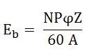
The magnitude of the back emf is given by the same expression shown below.
Where Eb is the induced emf of the motor known as Back EMF, A is the number of parallel paths through the armature between the brushes of opposite polarity. P is the number of poles, N is the speed, Z is the total number of conductors in the armature and ϕ is the useful flux per pole.
A simple conventional circuit diagram of the machine working as a motor is shown in the diagram below.

In this case, the magnitude of the back emf is always less than the applied voltage. The difference between the two is nearly equal when the motor runs under normal conditions. The current induces on the motor because of the main supply. The relation between the main supply, back emf and armature current is given as Eb = V – IaRa.
This is dummy text. It is not meant to be read. Accordingly, it is difficult to figure out when to end it. But then, this is dummy text. It is not meant to be read. Period.
Please do not enter any spam link in the comment box. ConversionConversion EmoticonEmoticon