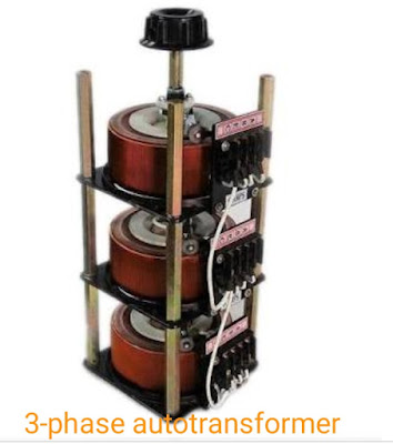
What is an autotransformer ?
An autotransformer is a kind of electrical transformer with only one winding. The "auto" prefix refers to the single coil acting alone, no to any kind of automatic mechanism. In an autotransformer portions of the same winding act as both the primary and secondary winding sides of the transformer.
On load condition , a part of the load current is obtained directly from the supply and the remaining part is obtained by transformer action. An autotransformer works as a voltage regulator. But in two winding ordinary transformer two different winding are used for primary and secondary purpose.
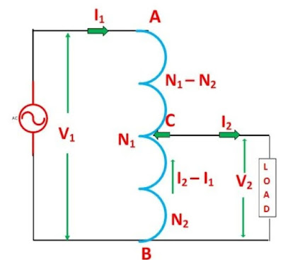
In an ordinary transformer, the primary and secondary winding are electrically insulated from each other but connected magnetically. And the other hand autotransformer the primary and secondary winding are connected magnetically as well as electrically. A circuit diagram of autotransformer is shown below.
 |
| Auto - transformer |
The primary winding AB of total turns N1. The primary winding is tapped and it's tapping point C is taken. And CB acts as a secondary winding. Let's assume the number of turns in between points B and C is N2.
The supply voltage is applied across the primary winding AB like ordinary transformer. And load is connected across the secondary winding CB. The tapping may be fixed or variable. When an AC voltage V¹ is applied across AB , an alternative flux is setup in the core, as a result, an EMF E¹ is induced in the winding AB . Apart of this induced emf is taken in the secondary circuit.
Let,
V¹ - Primary winding applied voltage.
V² - Secondary winding voltage across the load.
I¹ - Primary winding current.
I² - load current or secondary winding current.
N¹ - Number of turns between A and B.
N² - Number of turns between C and B.
Neglecting no-load current, leakage reactance and losses.
V¹=E¹ and V²=E²
Therefore, the transformer ratio :-

As the secondary ampere turns are opposite to primary ampere turns, so the current I² is in phase opposition to I¹. The secondary voltage is less than the primary. Therefore current I² is more than the current I¹.
Therefore, the resulting current flowing through section BC is ( I² - I¹).
The ampere turns due to section BC = current × turns


Please do not enter any spam link in the comment box. ConversionConversion EmoticonEmoticon